Finding the Treasure
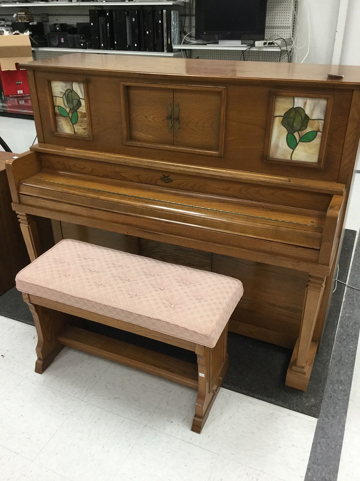
Universal Player Piano found at a thrift store. The piano was in pristine condition but the player portion was nonfunctional.
$50 Bucks?
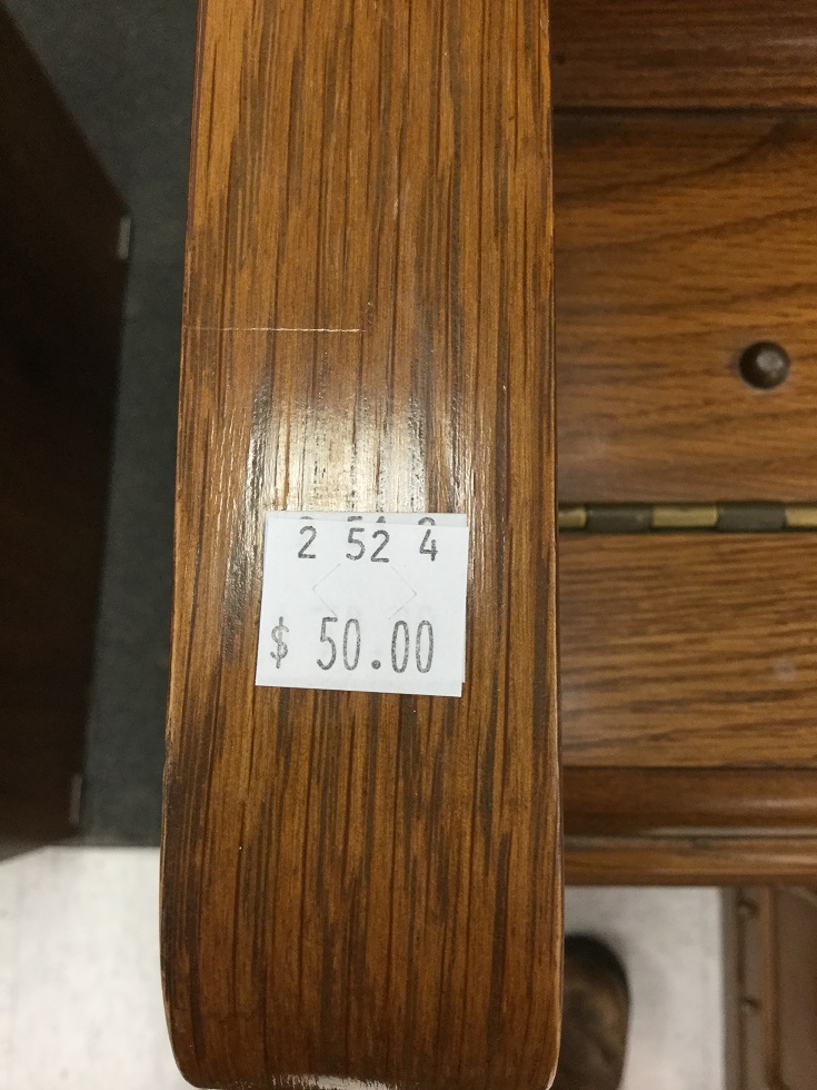
The price was changed from $75 to $50. Bought it on the spot.
Model

Make, Model and manufacturer of piano, plus the serial number.
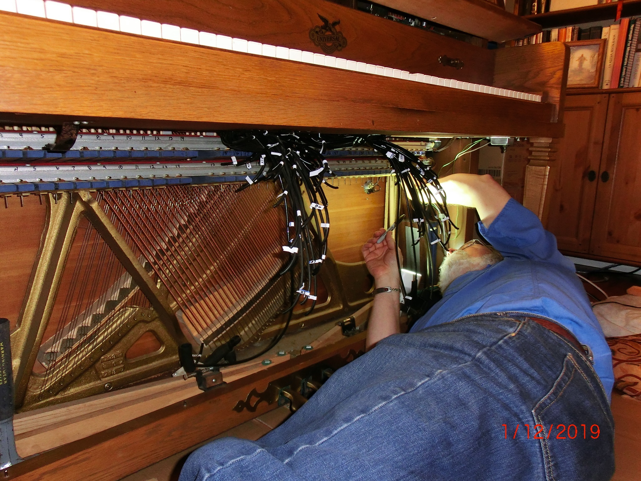
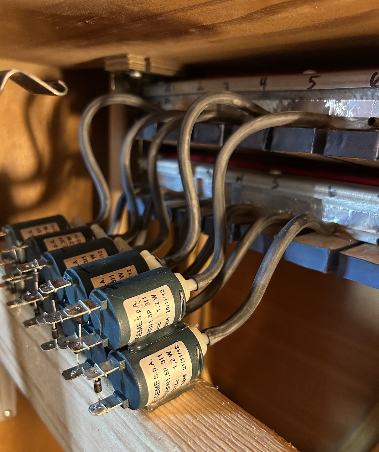
Actuation Bellows
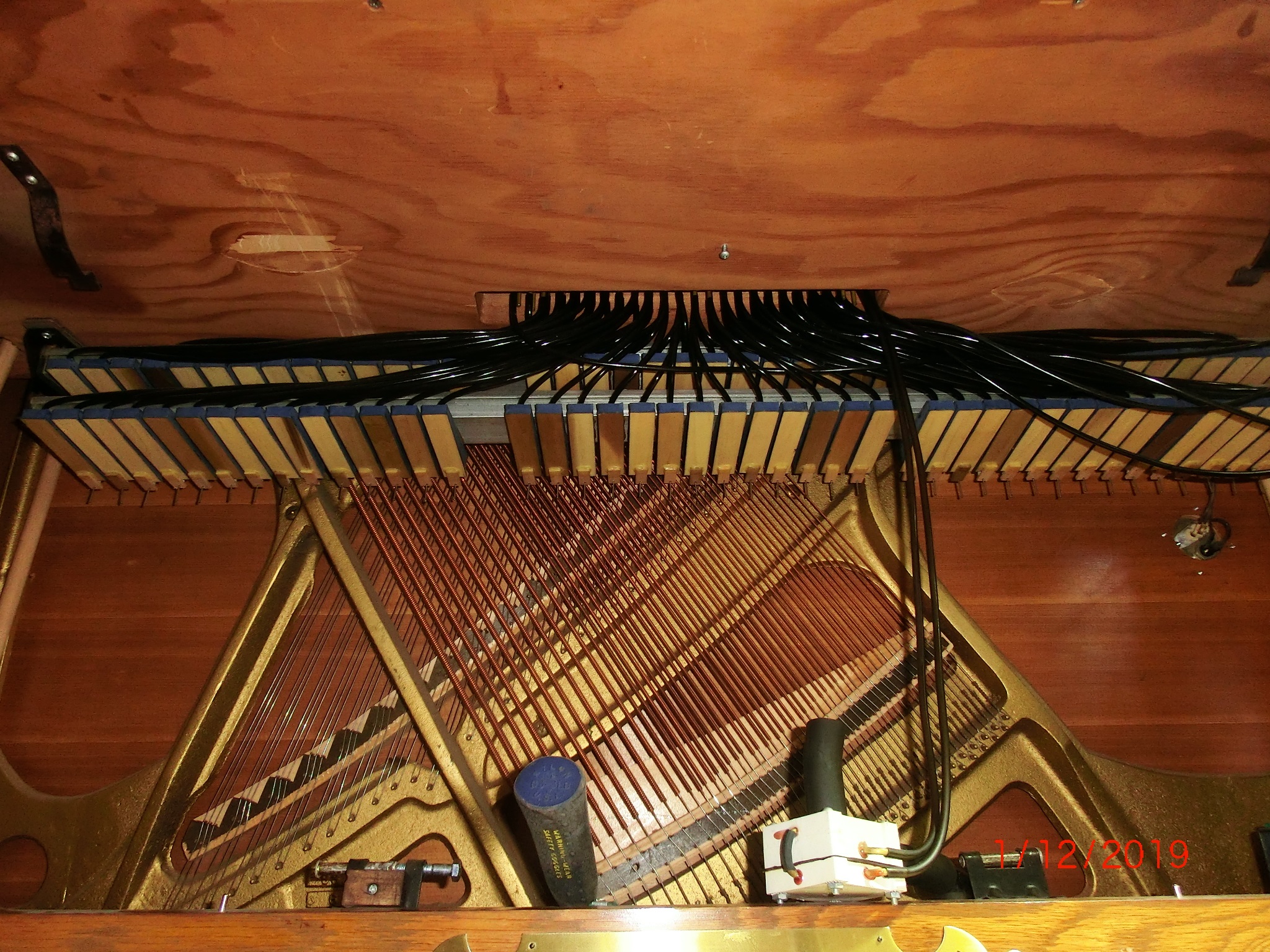
Actuation bellows manifold located under the keyboard platform.
Air Tubes Galore

Disconnecting and labeling tubing from paper platen from each actuator. The double stacked aluminum actuation manifold can now be seen.
Air Tube Interface Through keyboard
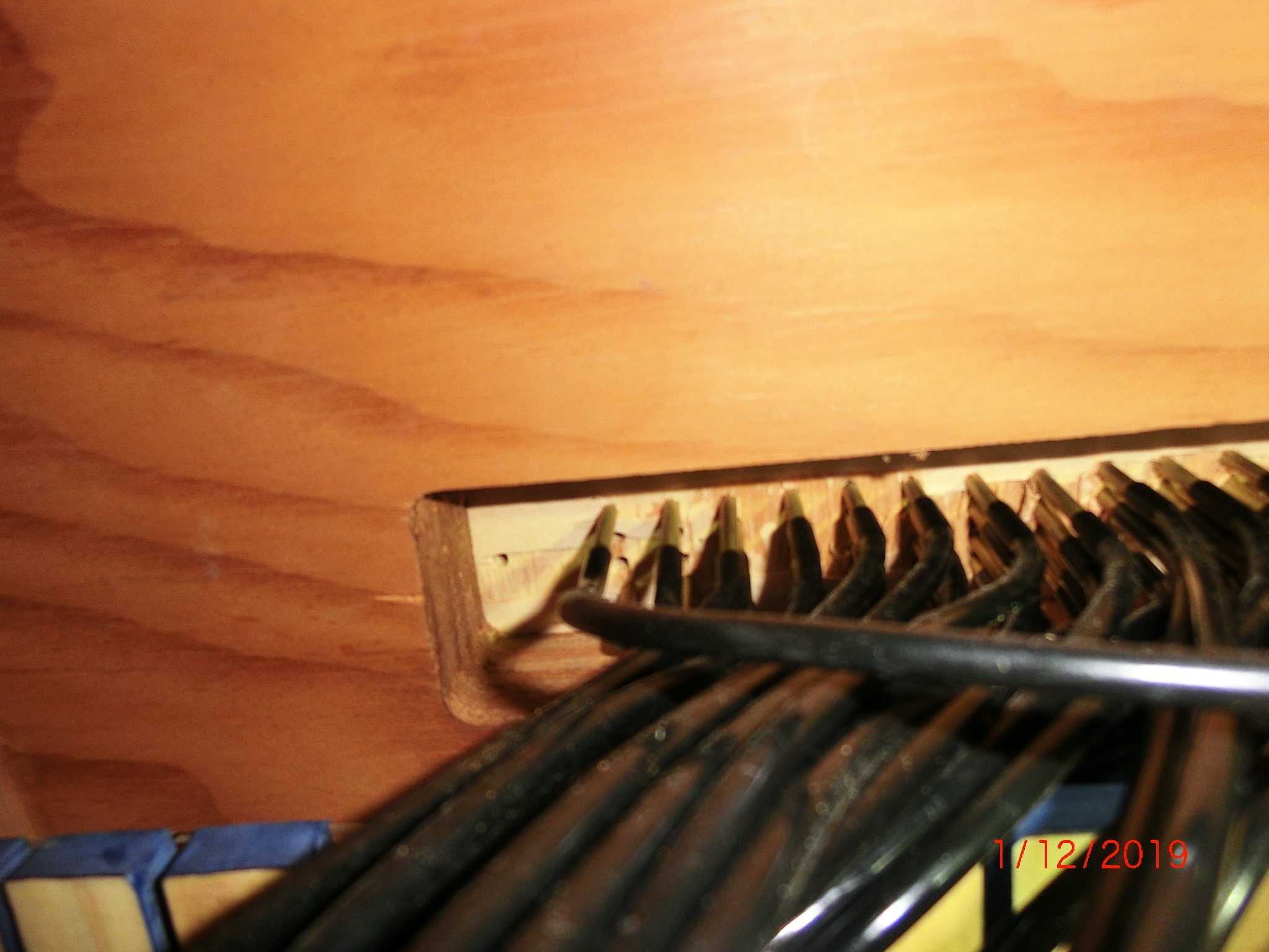
Each tube goes to a feed-thru on the keyboard platform in sequence.
Crawling Under
Loosening the double stacked manifold holding each key bellows.
On the Surgery Table
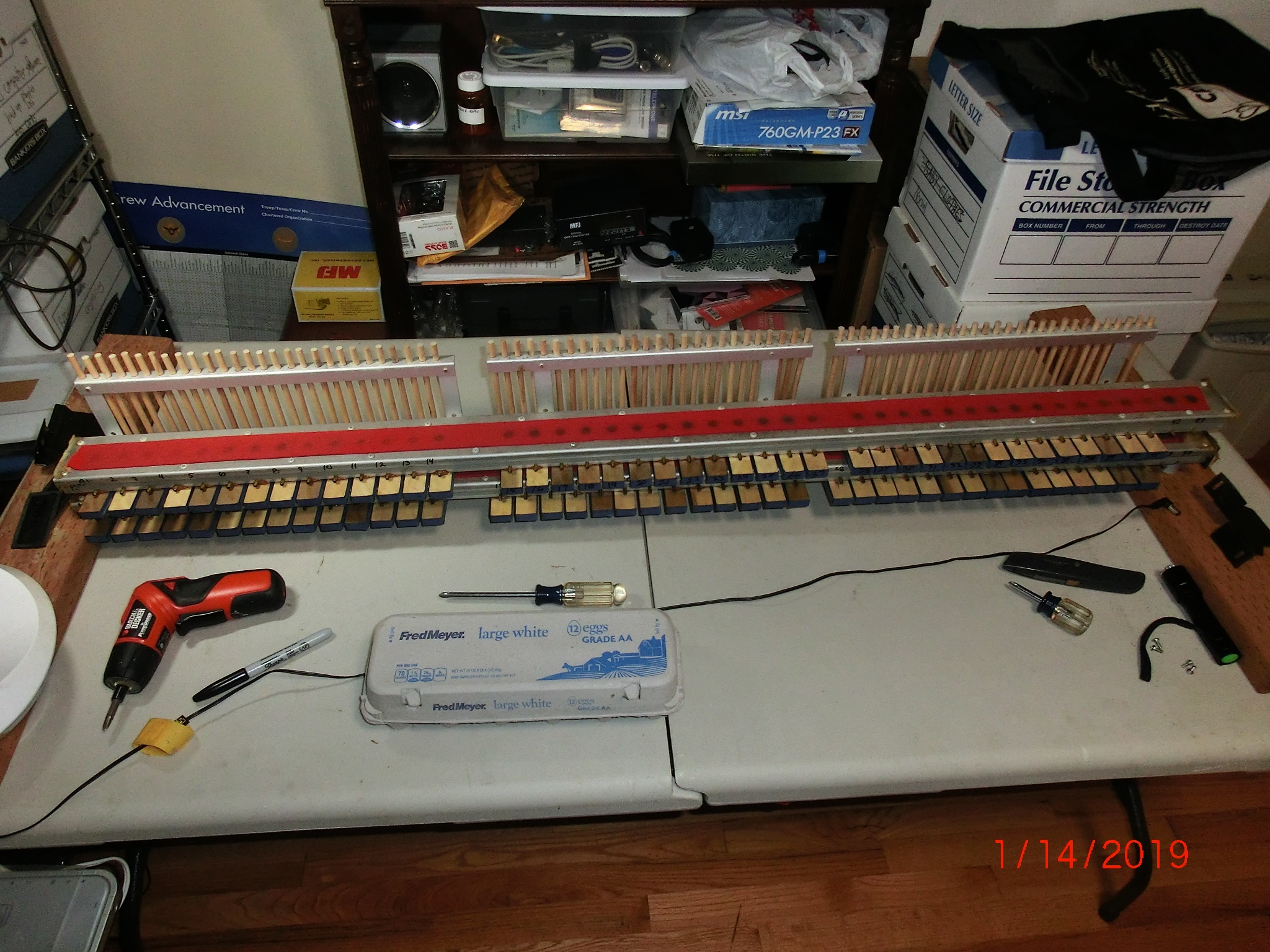
Removed double stacked manifold to the workbench.
Major Surgery
Removing the key stickers which push on each key.
Major Surgery 2

Separating the double stack manifold into two sections. Removing muffler felt
Original Pouches

The main reason this piano would not play is these ‘pouches’ were all leaking. You can see the tears around the edges of the white ring insert. A simple fix to these ‘pouches’- just has to be repeated 84 times.
Major Leaks

All pouches were repaired. Now the cleaning off of the old material.
Paper Dust?

All the diaphragms have been removed and the dust blown out this manifold is ready for reassembly.
New Supple Leather

Each diaphragm ‘pouch’ is carefully domed so there is a small amount of flexing to move the air-gate.
Expensive Leather

My 0.032 German leather used as pouch material carefully cut and glued to each pouch ring.
Cut & Paste

Clamping the glued leather to each pouch ring.
Specialty Tools

Carefully installing each pouch ring into the air manifold with glued pouch leather.
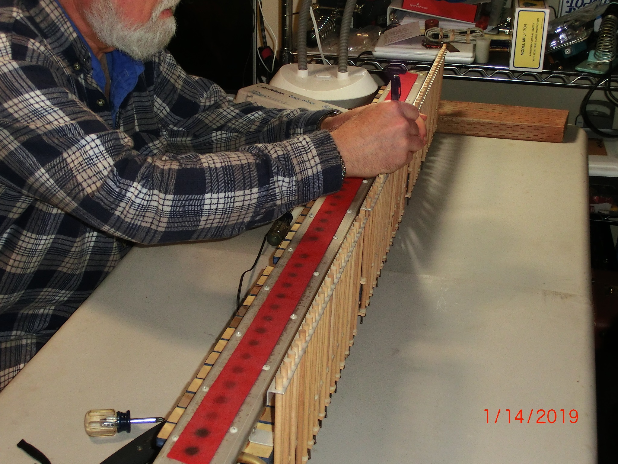
All Together Now

Double manifold actuation stack reassembled with key stickers on the back rail ready for installation into the piano and all the tubing reconnected.
Air Leaks?
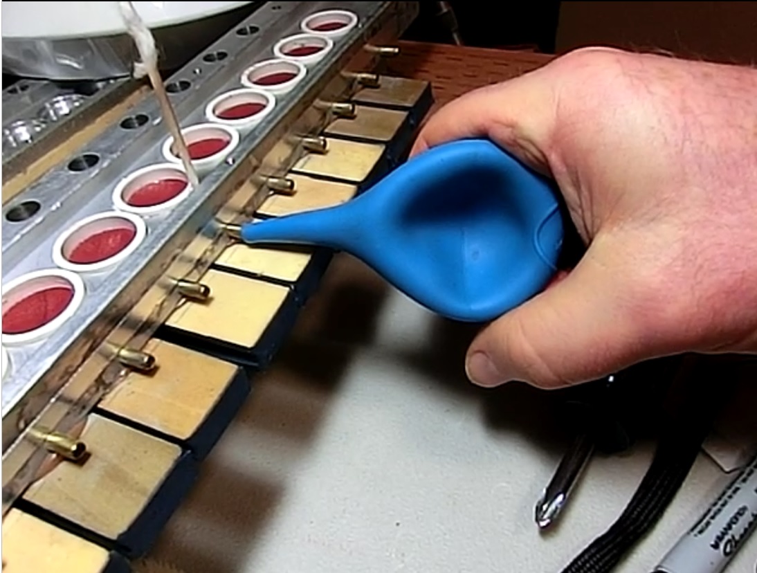
Leak test each bellows port. The bulb should stay collapsed for at least 3 seconds.
It passed at 6 seconds.
Above the Keyboard

All the tubing from the actuation to the player portion above the keyboard.
Below the Keyboard

Reinstallation of double stacked air manifold successful. Now, reconnect each tube from the paper platen above the keyboard.
All 84 Tubes

All the tubes reconnected to the double stacked manifolds. At this point the piano is ready to be put back into service.
The Main Objective
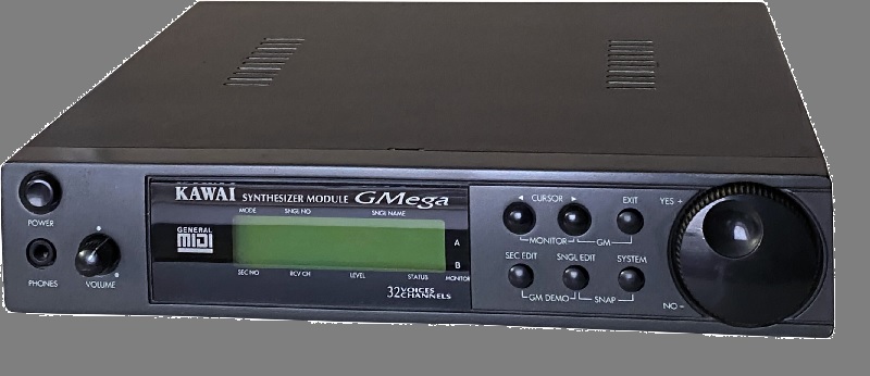
What follows is the idea of integrating this player piano to be used with a MIDI interface. MIDI is a Musical Instrument Digital Interface that sends out NOTE and VOLUME commands to a MIDI connected device, such as an electronic keyboard. A MIDI program generally runs on a PC but can be any form of controller. There are several devices that can be controlled through MIDI, such as sound modules (above) Capable of 16 MIDI channels and 128 pre-sampled instruments and played through a standard audio amplifier. My aim is to automate my player piano to be connectable to a MIDI controller- PC or MIDI controller.
Piano Paper?
The way a player piano operates is quite simple. Each key had a bellows that collapses pushing on a key on the keyboard playing a note. A paper roll as demonstrated in the above video clip: Flight of the Bumble Bee
Air Switches?
Next was to find a method to mimic the holes passing over the paper platen and port the vacuum to each key. It turns out that a small solenoid from Mr. Coffee coffee maker which ports water into the percolator was exactly what was needed. I created a driver circuit to test the speed this solenoid could operate.
Air Switch Test

Next connected this solenoid to a single key.
Key Solenoid
Even though I used a 9V battery, the solenoid opened and closed and actuated the key as planned.
Buffering MIDI Data

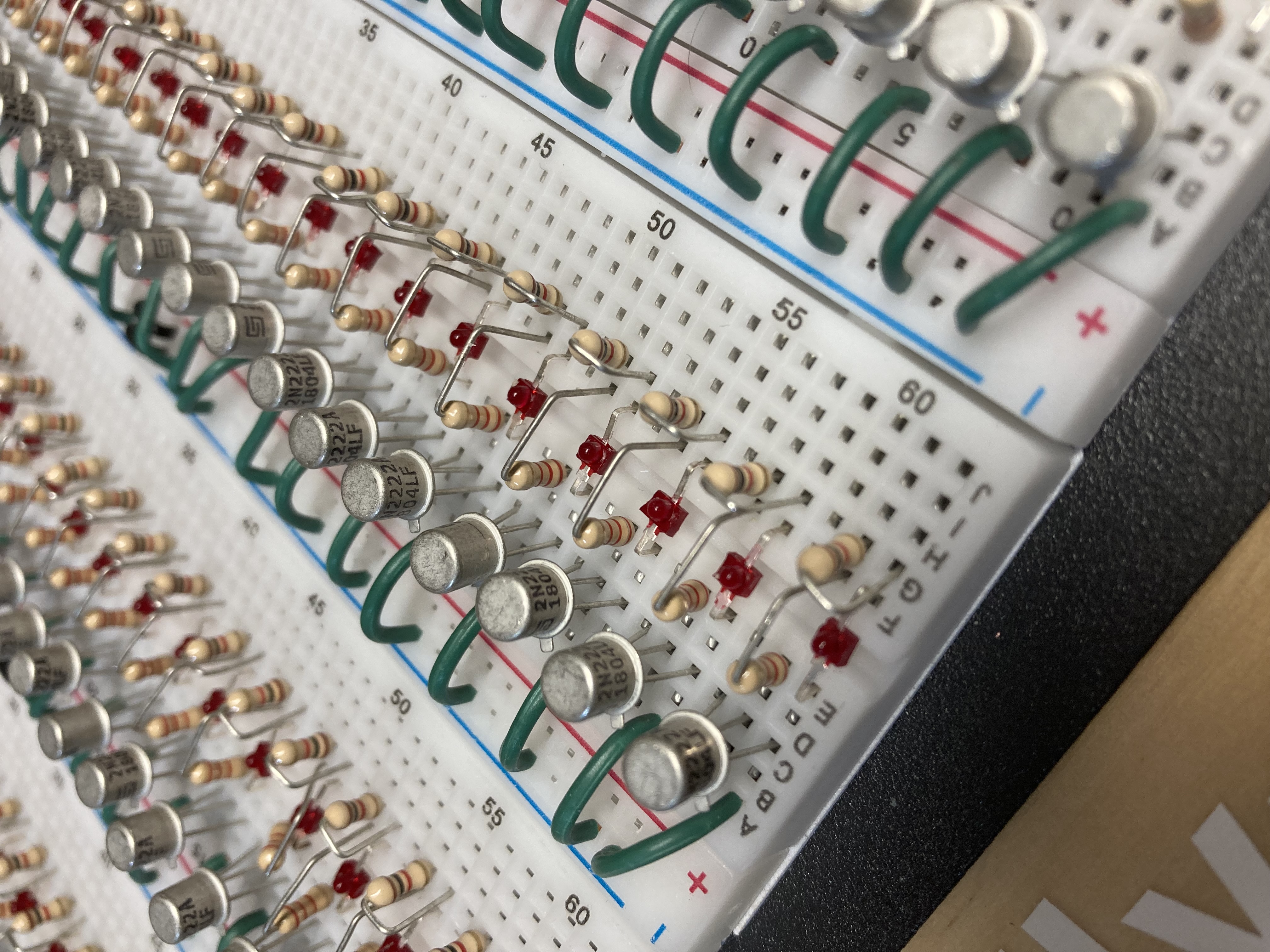
My own design included a collection of 11 x 8-bit shift registers which can accept MIDI data to into a single bit of faster than the fastest clock rate of the MIDI train of key and velocity data.
Line up the Buffers

Buffer used: Two of 11 shown.
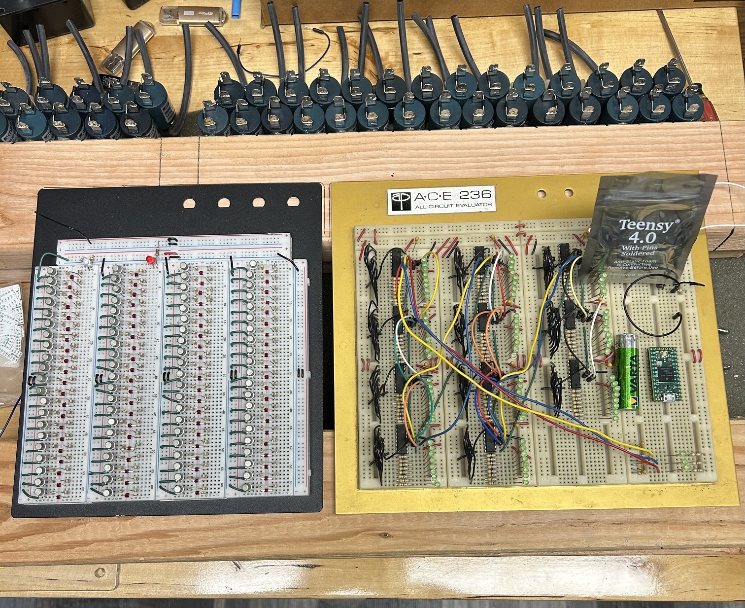
Did Someone Say Bread?

The cascading 11-8-bit buffers were placed on a breadboard for proof of concept.
Micro MIDI Controller

An Arduino micro controller (MicroView) had sufficient speed to accomplish buffering all 88 key actuations within the rate MIDI data is transmitted.
The MicroView is the first chip-sized Arduino compatible module that lets you see what your Arduino is thinking using a built-in OLED display. (Circa 2019) ATMEL’s ATmega328P, 5V & 3.3V LDO and a 64x48 pixel OLED display
Coil (solenoid) Driver Circuit:
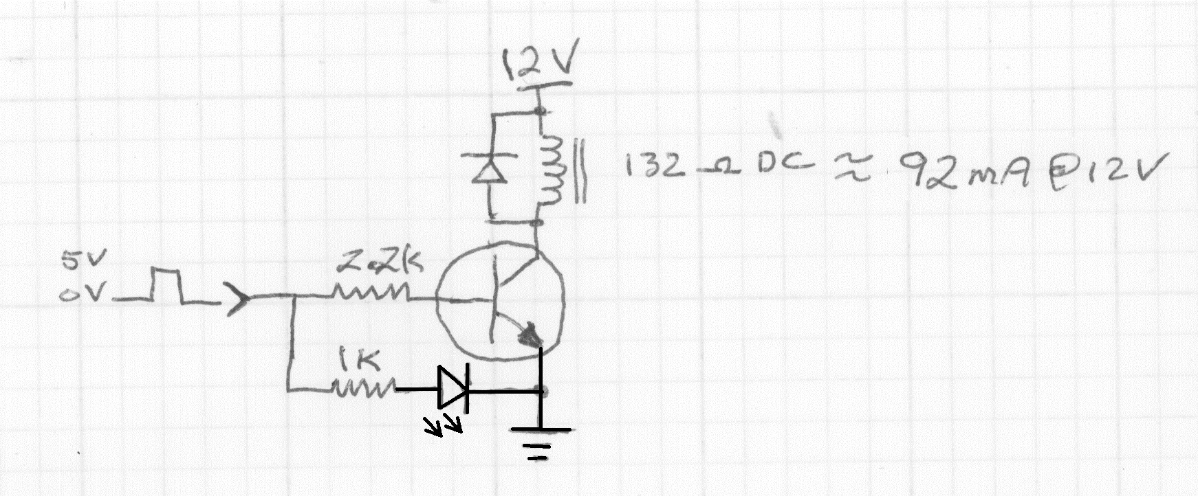
This includes a flyback damping diode across each solenoid to prevent the 90-100V spike from damaging the transistor which is only rated to 45VDC.
MIDI Decoder
The 8-bit buffers and MicroView were bread boarded for proof of concept. My HP Laptop provided the MIDI data through the opto-coupler.
The solo part was on one MIDI channel while the background accompaniment was all on different MIDI channels. The drums were on the same MIDI channel as the solo part. Hence you can see the drums appear on the green LEDs.
MIDI Channels
This is 4-part harmony with ALL the notes in the same channel. The MIDI specification, Ver 1.0, originated in 1992. There is now a MIDI 2.0 which has added many different capabilities. The fastest rate for MIDI interface data is 31,250 bits per second, which is equivalent to 3,125 bytes per second. This rate applies to standard MIDI interfaces using 5-pin DIN connectors. While USB MIDI interfaces are significantly faster, the standard MIDI specification limits the DIN cable rate to 31,250 bps. The Arduino MicroView far surpasses that data rate over USB data. So, each of the 11-8-bit shift registers need to be coupled to a single solenoid driver on this board.
Bus Drivers?

The Arduino can load ALL 11-8-bit data buffers in less than 2uS which is 500KHz or 16 times faster than the MIDI data is being parsed in the Arduino incoming buffer. Plenty of overhead room. If you remember the green LEDs on the breadboard- these were one of the 88 MIDI key ON/OFF commands.
Single Drivers (Close up)
All the Solenoids in one place

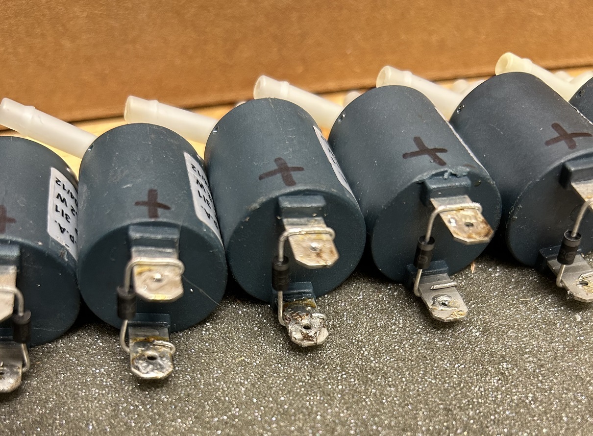
Here are the 84 solenoids that need to be “T’d” into the tubes leading to the actuation double manifold and mounted inside the piano.
All lined up for mounting.

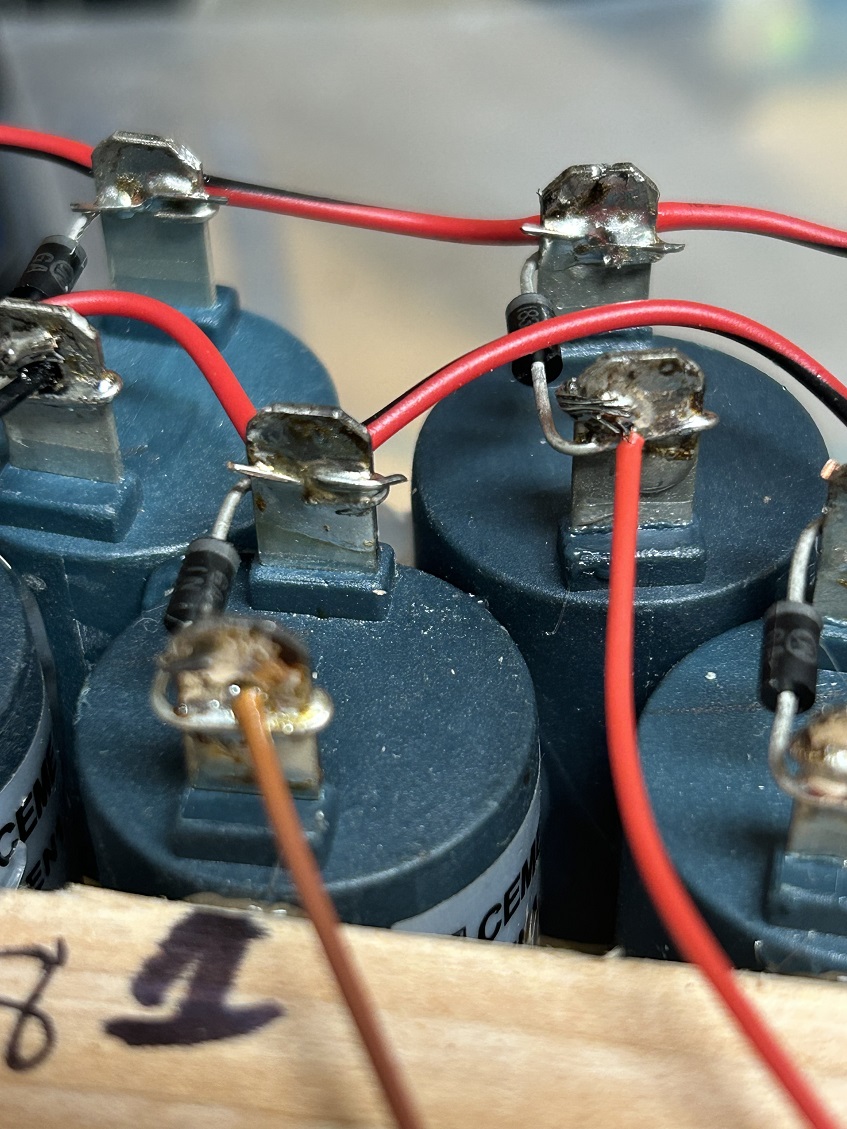
All the solenoids have their supression diodes. I had trouble with the math: 5 x 17 = 85. I only need 84.
A bad one???

I had a bad one! Not to worry. I have 10 spares.
Dead solenoid

I thought about opening it, but it is potted plastic and cannot be opened.
Diode Beads...

Close up of the supression diodes. They look like little beads on a silver wire. The orientation is critical because the fly-back voltage is in one direction and this diode takes the brunt of the voltage spike that would otherwise ruin the driver transistors.
Solenoid Test Jig

This is my critical test setup. I apply the 12VDC to the solenoid and watch on the scope for any fly-back voltage.
Diodes x 85 times...
All tested. The diodes are not soldered yet, just mechanically fastened. I'm going to have another wire soldered to these connections. Didn't want to heat the terminals too many times for fear of melting the plastic case.
Solenoid Template

Checked the tension of the tubes for proper fit with no leaks.
Template In Place
Installed the template to check the tube distances and if the bends would kink the tubes. All looks good!
Software?
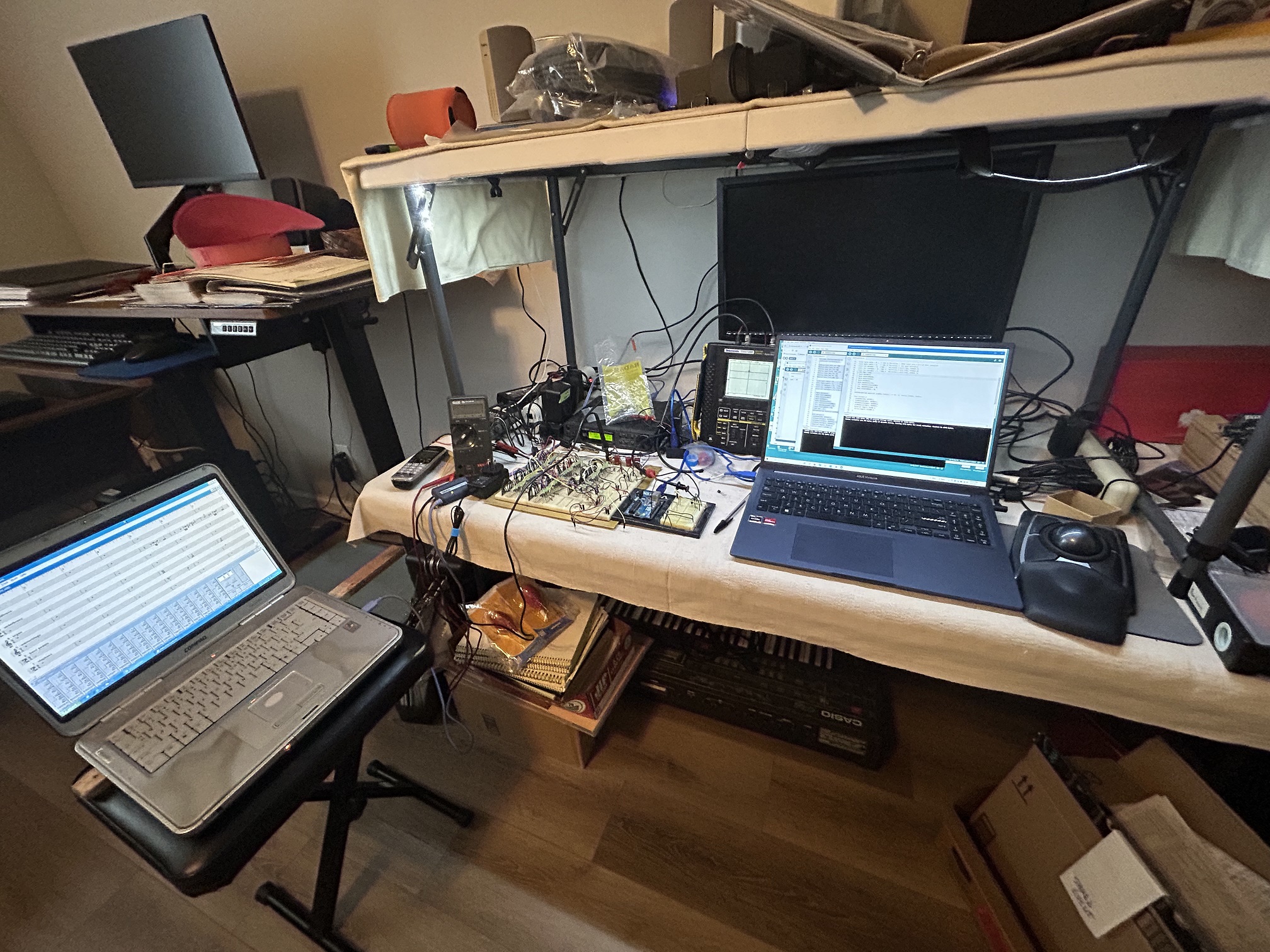
This is my software development bench. Turns out, the original MicroView I started with had some serious issues with receiving the MIDI data through a function called Software.Serial. The MIDI would easily get out of sync and the decode would stop.
Another Controller?
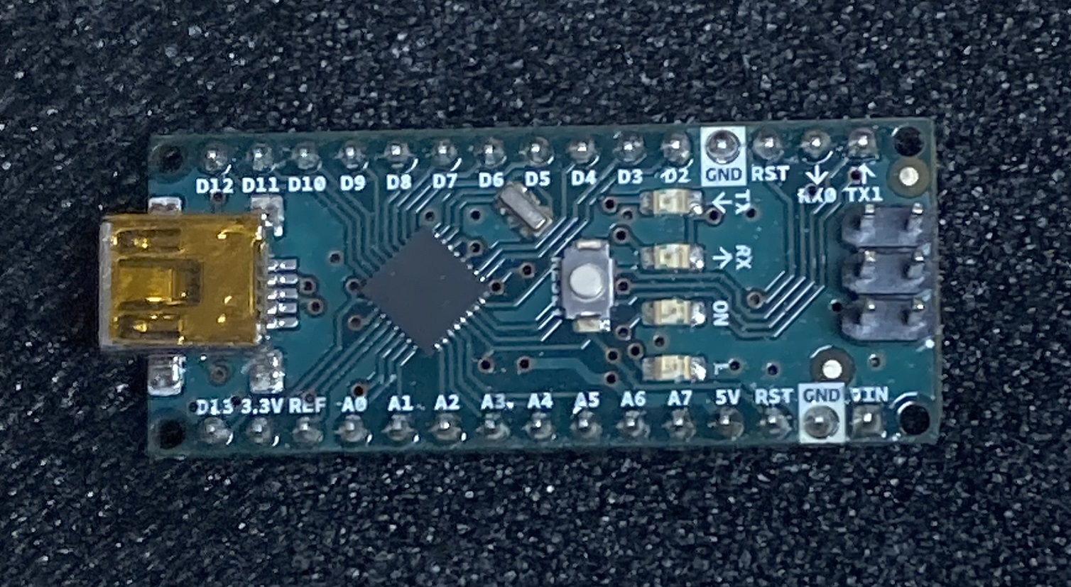
I thought another controller would have better stability. However, discovered there wasn't enough horse power in the UNO processor to maintain the speed necessary to successfully decode the MIDI stream.
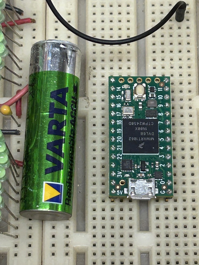
Enter the Teensy 4.0 World

The capability of this controller is almost 2000 times faster than any of the previously attempted controllers. Truly amazing.
Size of Teensy Controller

AA battery for size comparison
Transistors?


This new processor worked on 3.3 volts instead of the regular standard 5 volts most logic uses. Also, the outputs had an opposite logic sense, that is, when HIGH = 1, it was LOW instead. This is negative (inverse) logic. I had to build a voltage level shifter (to 5 volts) using transistors. It ended up that one transistor was not switching fast enough. So, I experimented with a double amplifier with two transistors. The switching was fast enough. However, only from high to low. This left the rise time much too slow to trigger the 8-bit latches
Schmitt Triggers?

An integrated circuit called a Schmitt Trigger was employed. This took care of the level shifting AND made the rise and fall times suitable to drive the 8-bit latches.
Stack Spaces?


Checking out where the spaces are between the key bellows from the upper stack and lower stack.
Glueing (Stabilizing)

Lining up the solenoids for HOT GLUE. HOT glue is not an adhesive only a stabilizer. So, since there is no movement of these solenoids, gravity wins.
Lining up

Hot glueing the solenoids and installing the vacuum tubes to make installation easier when this is in the piano.
Integration time: Picaso’s Spider? (Before & After)
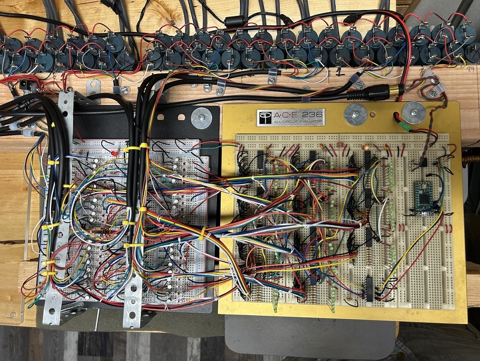
All wired up. 4 days of wire stripping and tinning with solder.
Getting connected

Every solenoid had to be connected: All the Plus voltage sides into 4 different arrangements so there would be no voltage drop on any section of 15 solenoids. See the little red wires on the table and in the round white lid? Those are wire-strip ends. All 168 ends of wires needed to be stripped. Took a couple of days.
Everything by “8’s”

Sequence: Brown, Red, Yellow, Gray, Green, blue, White, Black. The shift registers have 8 outputs so I can keep track of where the wires go. All the tips of this stranded wire had to be tinned. The wire tip’s plastic coating and infused with a tiny bit of solder to fit into the driver bread board. Another couple of days work.
Soldering Magic

I have a soldering pistol (gun, as it used to be called) that the tip had opened up. Anything contacted between those open tips immediately gets hot enough to solder. Nice shiny connections as a result of higher heat. If I had done this with my regular 35 watt soldering iron I would have melted the blue plastic these solenoids are made from.
Sparking Soldering?
The low voltage of the output has high current which heats the item it connects to. The sparking shows the current intensity.
WIRED


The MIDI decoder breadboard (nearest) is now wired to the solenoid driver breadboard which is now all wired to each solenoid. Ready for install!
Clicking-Clacking
Initial checkout of a single 8-bit shift register circuit chain from controller to solenoid.
Full Up Latch & Driver Test
Initial checkout of a single 8-bit shift register circuit chain from controller to solenoid.
Checking Drivers
The controller software, called a sketch, is now sequencing the 8-bit shift registers from 1-84 to check out the entire circuit to the solenoids.
Installation
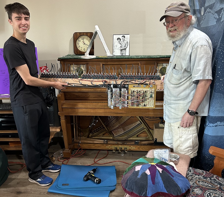
It weighs almost 30lbs
Vacuum Tubes?

My grandson climbed up practically inside to connect the vacuum tubes to the individual key bellows. (Did he say “Vacuum Tubes?)
Both of us getting in the act!
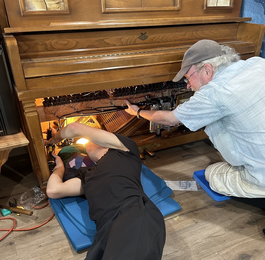
I’m holding while my grandson is drilling the screw holes for the fasteners.
Installed

All mounted and ready for checkout.
Sequence each key
OH OH – got a tube mis routed. Stepping backwards near the top which is after the 3rd break of the key bellows. It was the portion “I” connected. DOH!
Now we got the right sequence
You can see all the debugging LEDs I installed to know if the 11 latches were in sequence with the driver board and solenoids.
Inaugural Song
This was actually a song my grandson has been practicing. He found the MIDI file so he could hear the speed it’s supposed to be played. I’ll put the whole song at the end for your enjoyment.
Roll Over Beethoven has a new meaning now.
This is Fur Elise at 240 bpm (Beats Per Minute)
Another inauguration song
This one tested pretty much the speed and attack of each key through trills and ‘multi-hand’ playing of the keyboard.
Beethoven at normal speed
Sweet...
Unused keys: Used for paper rolling control

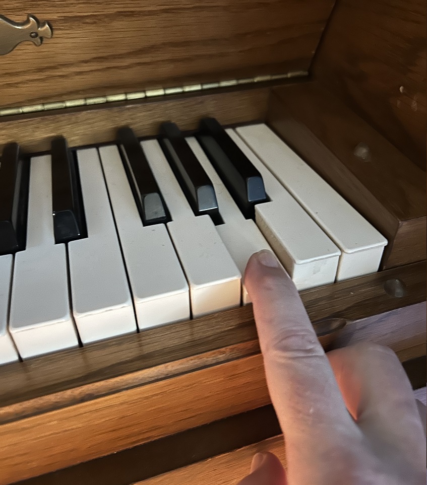
The unused keys are for the regular paper rolling motor dynamics. When A0 (the very bottom key) is rolling on the paper it actuates the ‘Sustain’ pedal. When the top key (C8) is rolling on the paper it signals the motor to rewind the paper roll. The MIDI specification indicates that the very bottom key is note 20. My MIDI decoder specified ‘0’ as the very bottom note. So, in real life every note I was referencing was 20 notes too high. Even though my sequencer was playing the keys mapped correctly. The piano played everything almost 2 octaves high. So, I had to OFFSET my mapping of keys (minus)-23 which is 2 octaves. This made MIDDLE ‘C’ where it was supposed to be mapped according to the MIDI standard and offset according to my relative positional mapping. Pretty crazy, huh? I learned this after the fact. All in all, a pretty intensive assembly of parts and actuation to accomplish an imagination I had 7 years ago.
Here are other recordings of MIDI songs.
Flight Of the Bumble Bee...
Fantasy Impromptu, by Chopin
I hope you enjoyed this Journey like I did creating it.
For the technically inclined this is a captioned video of when the software was finally completed and played the song correctly.